Build your own!
Maybe
the dongle just disappeared without a trace one day when you needed it
most - they tend to do that. Maybe it got accidentally slammed in the
car door one time too many. Maybe the manufacturer is out of business,
doesn't sell replacement dongles, or wants to charge more for it than a
brand-new (or brand-used) card. Or, maybe you've recently picked up one
or more dongle-less netcards cheaply because you thought you could pick
up replacement dongles cheaply too, and now want to actually use them
:-)
This page will explain how to connect a large percentage of PCMCIA netcards to your network without using the factory-supplied dongle, as these parts have a tendancy to get lost, damaged or stolen, and for some cards, are extraordinarily difficult/expensive to find replacements for. The dongle has fast become one of the more annoying things (besides Microsoft) to enter the world of networking.
This page will explain how to connect a large percentage of PCMCIA netcards to your network without using the factory-supplied dongle, as these parts have a tendancy to get lost, damaged or stolen, and for some cards, are extraordinarily difficult/expensive to find replacements for. The dongle has fast become one of the more annoying things (besides Microsoft) to enter the world of networking.
Network Technology Crash Course
Wish you could learn all about the intricacies of twisted-pair
networking electronics on one short, easy-to-digest Web page? Well,
sorry to disappoint you - most people don't, so I will tell you only
the bare minimum you need to know to attach a homemade dongle.
This document assumes you are using 10base-T/100base-TX (twisted pair, with an 8-pin [RJ45] plug that looks like a large phone jack) networking hardware, as opposed to coaxial (which you could also make your own dongle for, but this document doesn't cover it).
For your basic 10Mb/sec Ethernet, only 4 of the 8 wires in the RJ45 connector are actually used: two for transmitting and two for receiving. The transmit and receive pairs are isolated from each other electrically. Both pairs are also isolated from the networking hardware (hub, switch, netcard) by a transformer as shown in this simplified diagram. (For anyone interested, this non-simplified diagram is also available courtesy of National Semiconductor.) What this all means is that your equipment will be protected somewhat against short circuits, reversing the wires, etc.

On the RJ45 socket, these 4 wires are arranged as follows:
So, that's all you need to know. Really :-) Now, let's build a dongle...
This document assumes you are using 10base-T/100base-TX (twisted pair, with an 8-pin [RJ45] plug that looks like a large phone jack) networking hardware, as opposed to coaxial (which you could also make your own dongle for, but this document doesn't cover it).
For your basic 10Mb/sec Ethernet, only 4 of the 8 wires in the RJ45 connector are actually used: two for transmitting and two for receiving. The transmit and receive pairs are isolated from each other electrically. Both pairs are also isolated from the networking hardware (hub, switch, netcard) by a transformer as shown in this simplified diagram. (For anyone interested, this non-simplified diagram is also available courtesy of National Semiconductor.) What this all means is that your equipment will be protected somewhat against short circuits, reversing the wires, etc.
On the RJ45 socket, these 4 wires are arranged as follows:
|
 |
So, that's all you need to know. Really :-) Now, let's build a dongle...
Make The Dongle
A
"real" factory-supplied dongle ends in a funny little plastic plug with
dozens of pins (usually hidden in a sheath), which clicks into the end
of your PCMCIA network card. Without very specialized equipment and a
CAD degree (and probably lawyers, once they find out you're duplicating
their funny plug), you're not going to be able to reproduce it.
Therefore, it will be necessary to open up the network card and wire
directly into its receive and transmit lines. This will require a
soldering iron and probably a fair amount of skill using one, as these
connections will be tiny.
Warnings:
This procedure requires you to take apart your network card and solder wires to its innards. Careless soldering or mishandling of the card may damage it. Extremely careless soldering, such as little random blobs of solder shorting across random connections inside your netcard, could even damage your network hub, PCMCIA slot and/or computer when the card is used.
This procedure should work on a majority of commonly-available network cards. However, it is not guaranteed! It is possible that you will run into problems, specific to your make and model of netcard, that have not been anticipated here.
The innards of your network card are sensitive to static electricity. Before you do anything else, touch a grounded metal surface at your work area to get rid of any stray static charges you might have accumulated.
Supplies needed:
The housing around a PCMCIA network card typically consists of a thin metal shell made up of 2 pieces, with metal tabs bent over and around the card to hold the shell on. Using your prying tool of choice, carefully bend these metal tabs back enough that you can pull the shell apart, exposing the circuit board. (Try not to bend things too much; remember that you will have to put it back together eventually :-)
Find the transformer and determine its output pairs
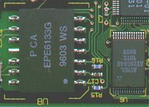
To determine where to attach wires, first you must find the output transformer. It is usually the largest component (or nearly largest) on the board, and is usually located near the connector where you would attach your real dongle if you had one. Since space is so tight on a PCMCIA card, the transformer will be very short to fit inside the shell, and will probably not look like any transformer you've seen before (it probably looks a lot like the rest of the chips on the board, but with bigger pins). A typical integrated transformer has about 10-14 pins, spaced further apart than a typical surface-mount microchip. The following image shows the integrated transformer from a 3Com 3c589 network card (on the left), in comparison with ordinary surface-mount chips to the right.
Warnings:
This procedure requires you to take apart your network card and solder wires to its innards. Careless soldering or mishandling of the card may damage it. Extremely careless soldering, such as little random blobs of solder shorting across random connections inside your netcard, could even damage your network hub, PCMCIA slot and/or computer when the card is used.
This procedure should work on a majority of commonly-available network cards. However, it is not guaranteed! It is possible that you will run into problems, specific to your make and model of netcard, that have not been anticipated here.
The innards of your network card are sensitive to static electricity. Before you do anything else, touch a grounded metal surface at your work area to get rid of any stray static charges you might have accumulated.
Supplies needed:
- Soldering iron
- Ohmmeter (or multimeter)
- Small flathead screwdriver, knife, pliers or other prying tools (to get the netcard apart)
- 4-conductor cable (preferred) or wires for attaching to your network card
- RJ-45 Connector
- Good eyes
The housing around a PCMCIA network card typically consists of a thin metal shell made up of 2 pieces, with metal tabs bent over and around the card to hold the shell on. Using your prying tool of choice, carefully bend these metal tabs back enough that you can pull the shell apart, exposing the circuit board. (Try not to bend things too much; remember that you will have to put it back together eventually :-)
Find the transformer and determine its output pairs
To determine where to attach wires, first you must find the output transformer. It is usually the largest component (or nearly largest) on the board, and is usually located near the connector where you would attach your real dongle if you had one. Since space is so tight on a PCMCIA card, the transformer will be very short to fit inside the shell, and will probably not look like any transformer you've seen before (it probably looks a lot like the rest of the chips on the board, but with bigger pins). A typical integrated transformer has about 10-14 pins, spaced further apart than a typical surface-mount microchip. The following image shows the integrated transformer from a 3Com 3c589 network card (on the left), in comparison with ordinary surface-mount chips to the right.
If
you look closely, you notice 4 green traces leading out of the left
side of the transformer. They lead ultimately (with a minimum of
side-trips) to the dongle connector. While a lot of other stuff also
leads to the dongle connector, these four are the lines that carry your
network data.
** No transformer on your netcard? If you looked and looked, and are certain there is no transformer on your card, you may be right. It might actually be inside the manufacturer's dongle, in which case you're out of luck. **
So, now you've probably narrowed things down to 4 wires. To most easily determine which ones go with which (e.g. the sending pair and the receiving pair), connect an ohmmeter across them. You will have to find someplace where each trace terminates in bare metal and/or a solder pad (for example, where they attach to the transformer). Little or no resistance (short circuit) across a given pair of wires indicates that they go together. Now you've narrowed it down to 2 pairs, but don't know which pair is for sending vs. receiving. At this time, you can fire up your soldering iron and solder in wires that connect to these 4 signal lines.
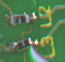
** This is very delicate work! Most, if not all, components in the network card will be tiny surface-mount parts all packed together pretty tightly. If they get too hot (e.g. from having a soldering iron near them too long) they can start floating around on their solder pads, as shown below: notice how the component marked "L3" appears crooked compared to L2 next to it. This image is taken from my own 3c589 card. (Try to be more careful than I was :-) **
Determine sending vs. receiving pair, and polarity
No easy ride here folks, you have to figure it out by trial and error. Luckily, we are down to only 4 possible ways you could hook them up. Now, plug your RJ45 connector into your network hub. With the card inserted in your computer, properly configured, turned on, etc., take the wires from pins 1 and 2 on the RJ45 connector (the Receive pair) and attach them to one of the pairs of wires you soldered in to the card. Watch for the "Link" light on your hub to come on. If nothing, reverse the wires and look again. If still nothing, repeat with the other pair until it detects your card.
You've now narrowed things down to 1 pair left to attach, and only 2 possible ways they could be hooked up. Connect the remaining wires to pins 3 and 6 on the RJ45 connector and see if your machine can access other machines through the network. If nothing, try reversing the wires you just hooked up.
Does it work?
If you have successfully connected to the network, congratulations! You can now make your connections "permanent" by either soldering the RJ45 to the wires leading out of your netcard, or attaching some kind of 4-conductor plug on each end so you can detach your network cable at will. On mine, I soldered matching plugs to the network card and a long Cat-5 cable ending in a RJ45 plug.
Once you are satisfied that everything works, mix up some epoxy and apply it liberally to hold all your wires and solder joints in place. This will prevent repeated bending and stress on your wires from breaking off any part of your delicate solder job. ** Epoxy is your friend.** If you soldered your own plug onto the other end, epoxy all the wires there too. Finally, reattach the metal "shell" around the card. It may be necessary to cut a little notch or hole in this metal to provide an exit for your wires.

Signal wires soldered in and fixed in place with epoxy
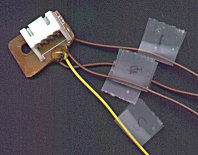
Custom plug attached to network card. Scotch tape "flags" were used to mark the signal lines during soldering.
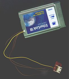
Finished product
** No transformer on your netcard? If you looked and looked, and are certain there is no transformer on your card, you may be right. It might actually be inside the manufacturer's dongle, in which case you're out of luck. **
So, now you've probably narrowed things down to 4 wires. To most easily determine which ones go with which (e.g. the sending pair and the receiving pair), connect an ohmmeter across them. You will have to find someplace where each trace terminates in bare metal and/or a solder pad (for example, where they attach to the transformer). Little or no resistance (short circuit) across a given pair of wires indicates that they go together. Now you've narrowed it down to 2 pairs, but don't know which pair is for sending vs. receiving. At this time, you can fire up your soldering iron and solder in wires that connect to these 4 signal lines.
** This is very delicate work! Most, if not all, components in the network card will be tiny surface-mount parts all packed together pretty tightly. If they get too hot (e.g. from having a soldering iron near them too long) they can start floating around on their solder pads, as shown below: notice how the component marked "L3" appears crooked compared to L2 next to it. This image is taken from my own 3c589 card. (Try to be more careful than I was :-) **
Determine sending vs. receiving pair, and polarity
No easy ride here folks, you have to figure it out by trial and error. Luckily, we are down to only 4 possible ways you could hook them up. Now, plug your RJ45 connector into your network hub. With the card inserted in your computer, properly configured, turned on, etc., take the wires from pins 1 and 2 on the RJ45 connector (the Receive pair) and attach them to one of the pairs of wires you soldered in to the card. Watch for the "Link" light on your hub to come on. If nothing, reverse the wires and look again. If still nothing, repeat with the other pair until it detects your card.
You've now narrowed things down to 1 pair left to attach, and only 2 possible ways they could be hooked up. Connect the remaining wires to pins 3 and 6 on the RJ45 connector and see if your machine can access other machines through the network. If nothing, try reversing the wires you just hooked up.
Does it work?
If you have successfully connected to the network, congratulations! You can now make your connections "permanent" by either soldering the RJ45 to the wires leading out of your netcard, or attaching some kind of 4-conductor plug on each end so you can detach your network cable at will. On mine, I soldered matching plugs to the network card and a long Cat-5 cable ending in a RJ45 plug.
Once you are satisfied that everything works, mix up some epoxy and apply it liberally to hold all your wires and solder joints in place. This will prevent repeated bending and stress on your wires from breaking off any part of your delicate solder job. ** Epoxy is your friend.** If you soldered your own plug onto the other end, epoxy all the wires there too. Finally, reattach the metal "shell" around the card. It may be necessary to cut a little notch or hole in this metal to provide an exit for your wires.
Signal wires soldered in and fixed in place with epoxy
Custom plug attached to network card. Scotch tape "flags" were used to mark the signal lines during soldering.
Finished product